Replacing the MTH Steam Engine "Curly" Tether
The purpose of this page is to show you step by step how to replace the "Curly" tether found on older MTH steam engines with a straight tether used on the MTH diesels.
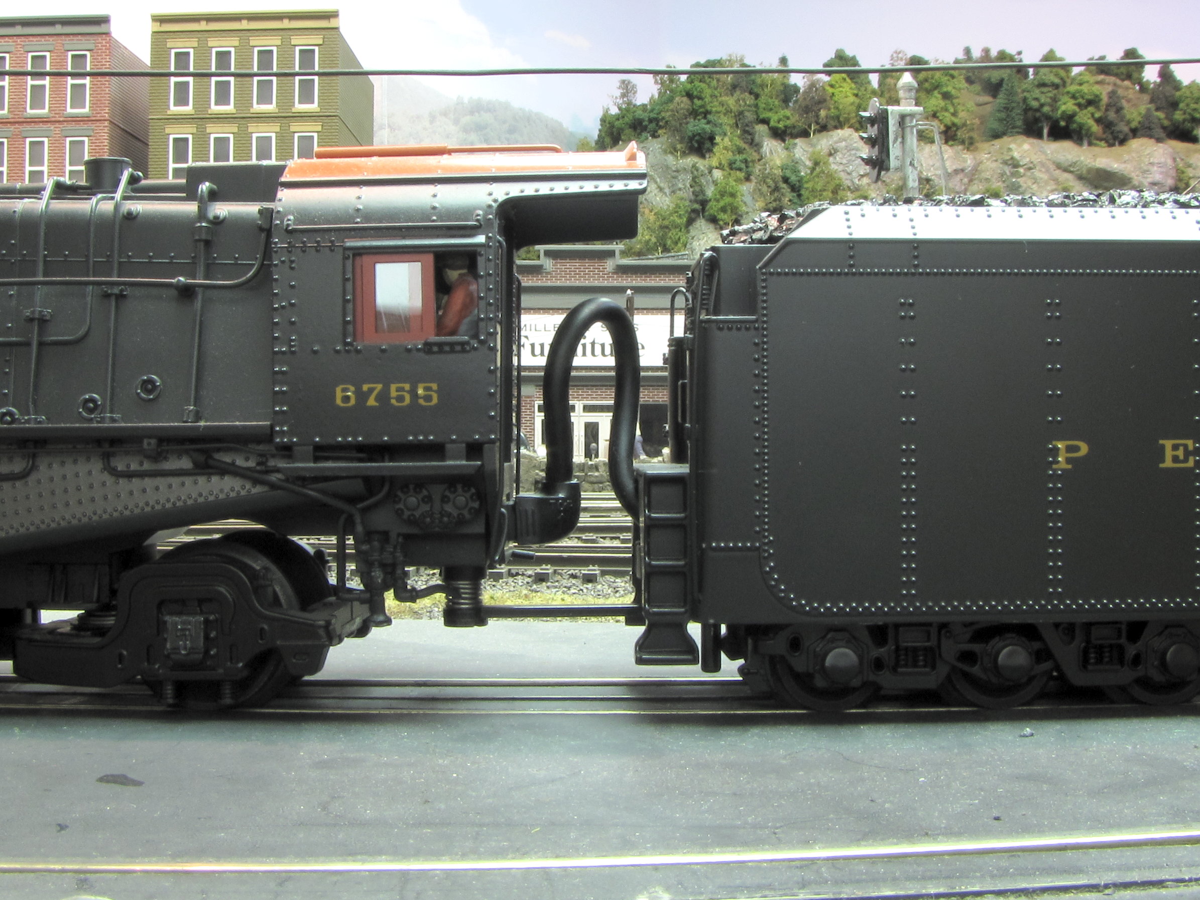
Replace "Curly Tether"
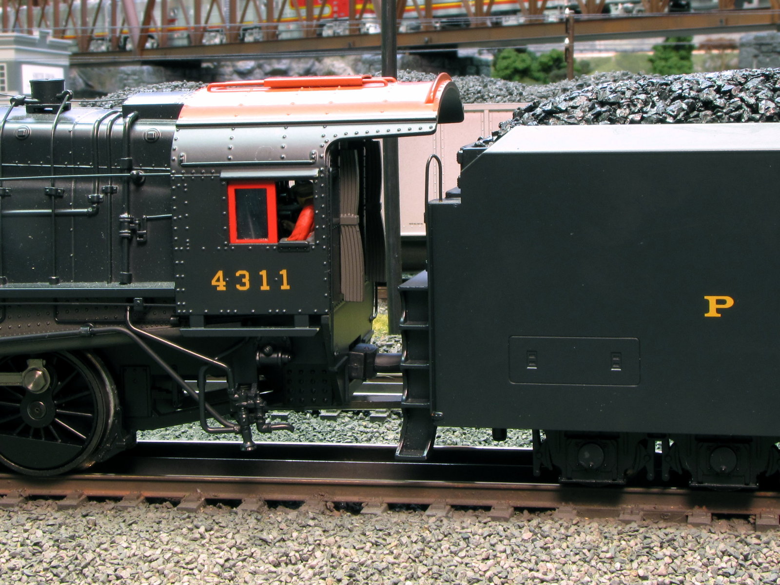
with "Straight" diesel tether
(Click on images to see larger photo)
WARNING: Modifying the engine in this way will likely void any remaining warranty you have on this engine. Although I have successfully done this modification with this engine there is no guarantee it will work and I take no responsibility for its outcome. Do this modification at your own risk!
Ok. Now that all the scarey words are out of the way, lets get down to modifying this engine!
The following are a summary of the steps need for this modification. Click on a section to jump right to it, or just scroll down through each section.
1. Purchase and test replacement cable
Unfortunately, the bag I received my straight diesel tethers in did not have a part number. You will have to call MTH parts department and ask for the diesel tether assembly shown below
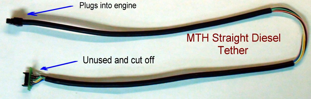
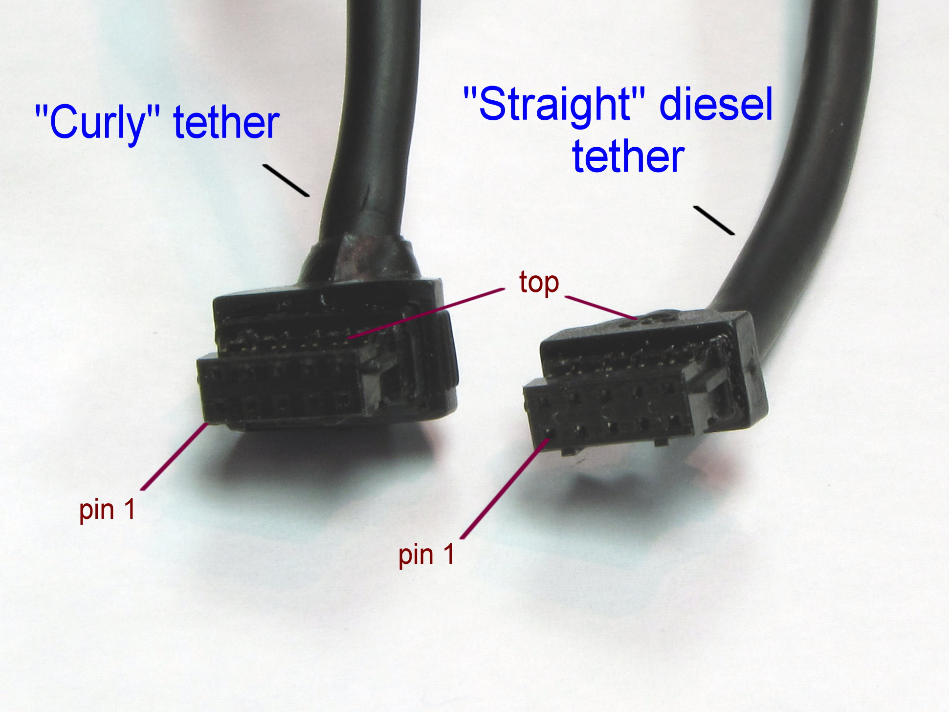
These cables use the same connectors on the engines side and have the same pinouts.
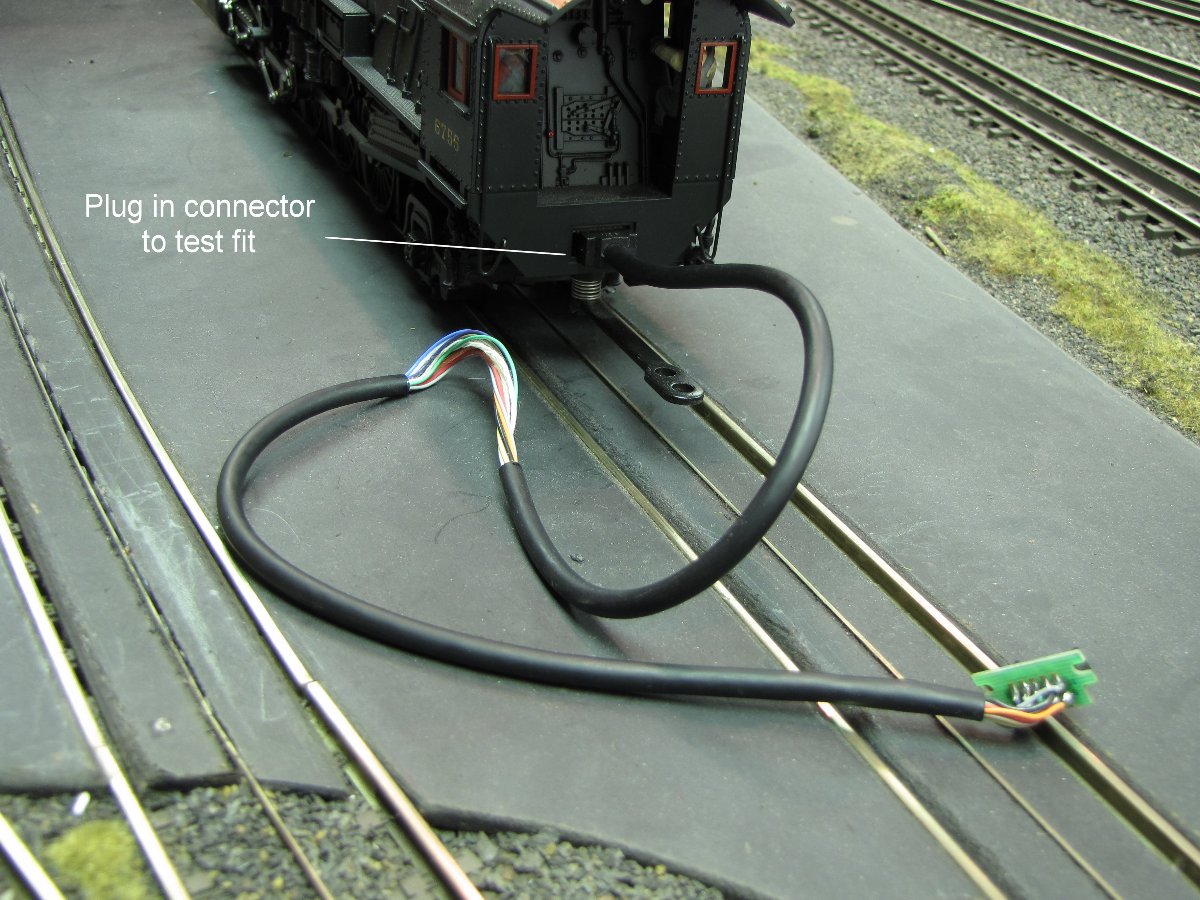
Plug in "straight" diesel cable to test connector to make sure it fits before making your modification.
(Click on images to see larger photo)
Requirements: Minimum O-72 curves are needed for this to work reliably. The reason for the "Curly" tether is to reduce the force on the connector during tight turns so it does not pull out. The worst are "S" curves which produce the maximum shift between engine and tender. If you have turns tighter than O-72 and "S" curves with O-72 or less, the connector may eventually come loose causing your engine to operate sporadically and uncontrollably causing it to crash. As you will see later I bore out the hole in the tender to allow more room for the "straight" tether to move which reduces the force on the connector through turns. This mod makes it work through my O-72 "S" curve, but margninally, and I plan on eventually removing the "S" curve.
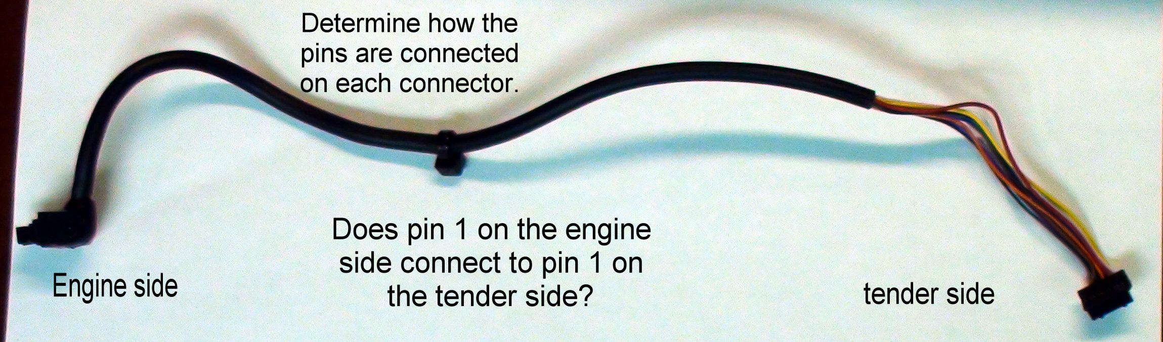
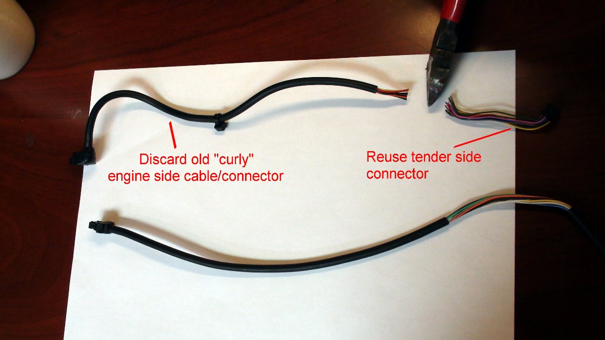
2. Map pins on existing "curly" tether
The goal is to determine how the pins are connected from the engine connector to the connector inside the tender via the existing "curly" tether. Don't assume that the pin numbers match one for one. In other words, don't assume pin1 on the engine connector goes to pin 1 on the connector inside the tether. Once we know how the pins connect, we can wire the new "straight" connector to make the same pin connections.
First remove the tender shell to expose the existing connector.
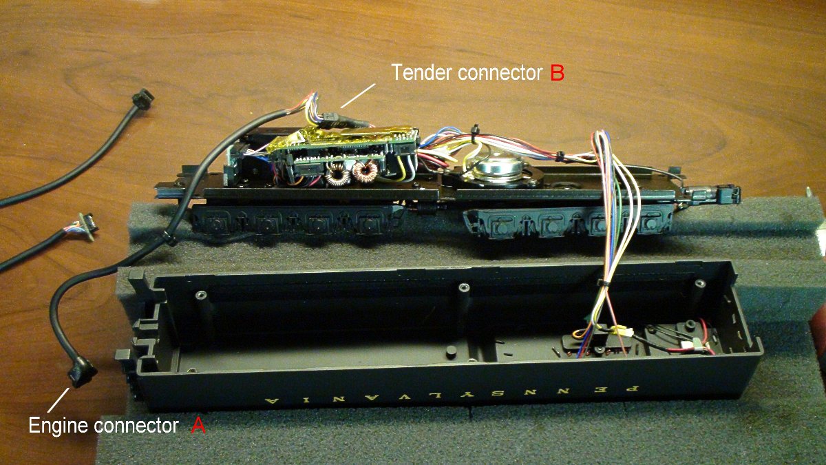
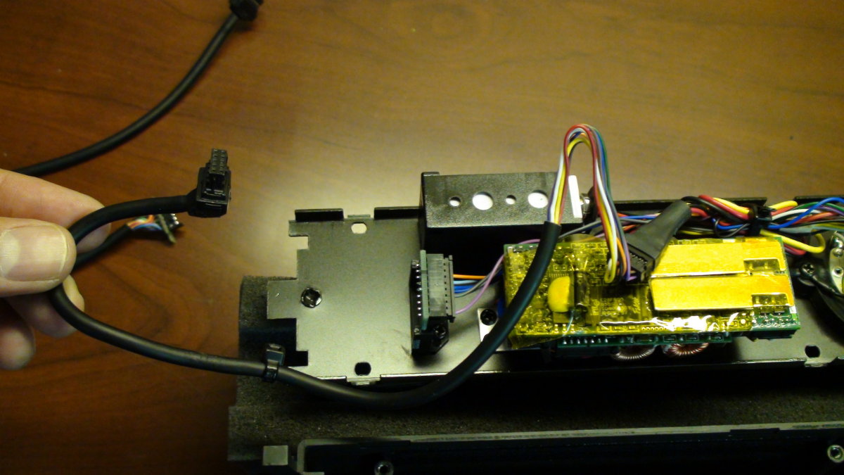
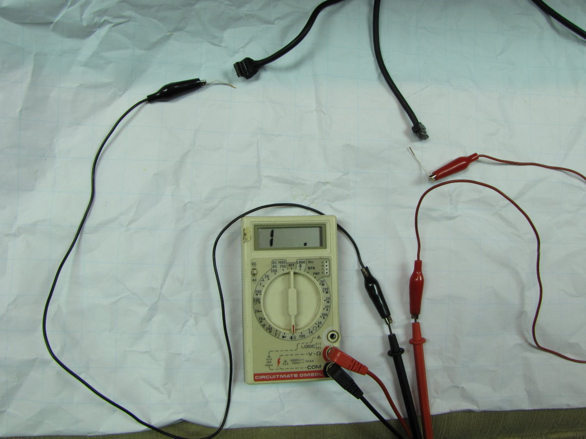
Unplug "curly" cable and determine pin connections between the engine side connector and the tender side connector.
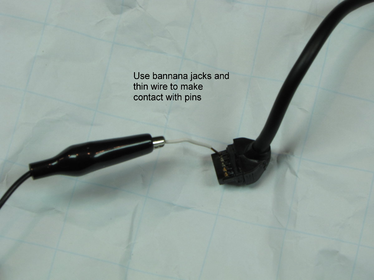
Use an ohmmeter to determine the pin connections between connectors. Use bananna jacks and thin wires to make contact with pins.
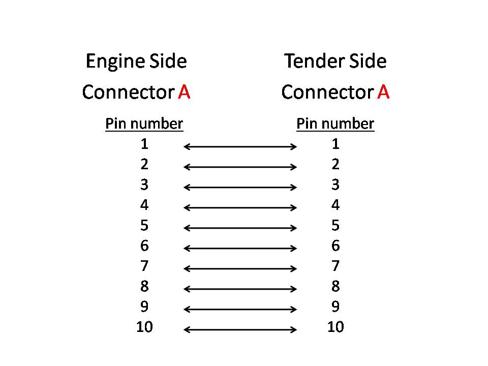
As it turns out, the pins on each connector matched one for one. You may get a different cable or your engine or tether may be wired differently so I recommend doing this procedure for yourself to be sure. The following are the pin connection between the engine side connector and tender side connector.
3. Map wire colors for each connector and build cable
Now that we know the pin connections between the engine side connector and tender side connector, we need to build a cable to make these connections. Since the other side of the new "straight" diesel connector does not mate up to the connector in the tender, we will cut it off and replace it using the tender side connector on the original cable.
Cut off original tender side connector.
(Sorry, connectors are hard to see on the right side of the photo)
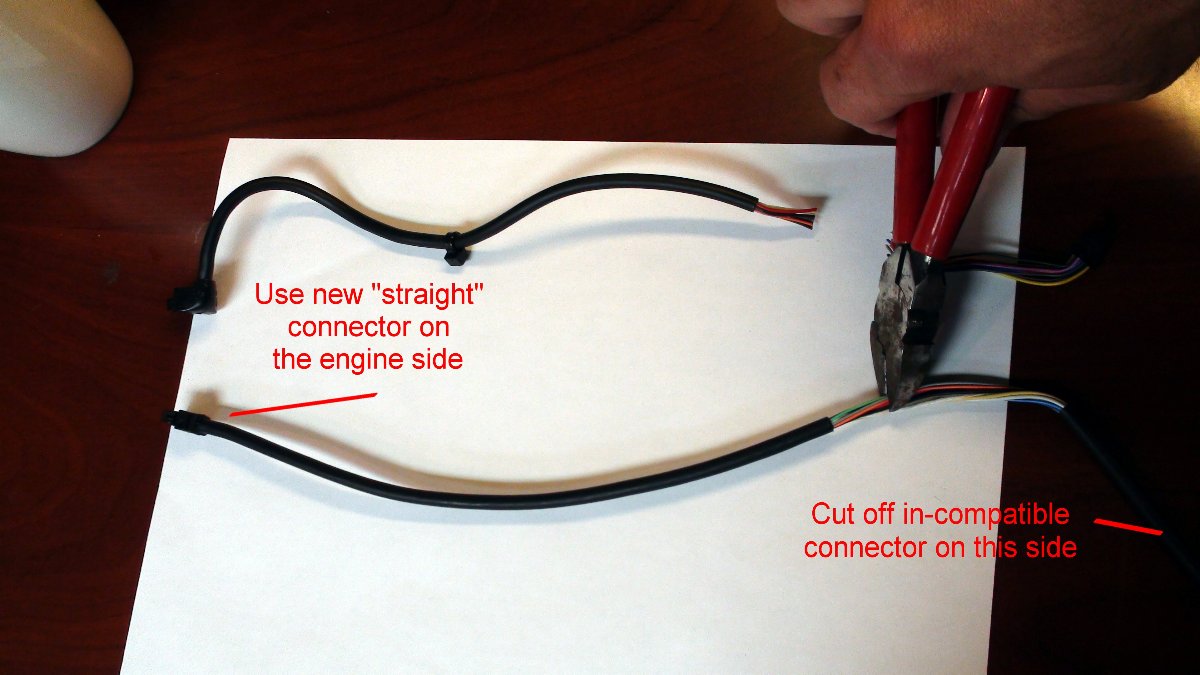
Cut off unused connector on new "straight" cable
Select new connectors
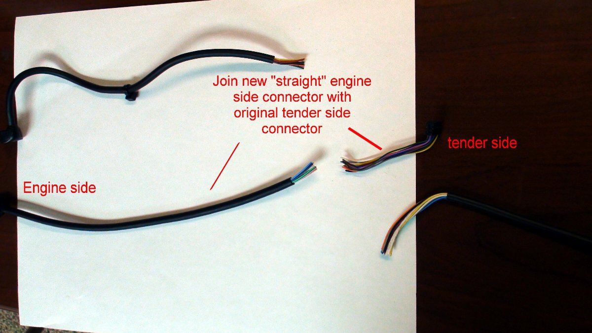
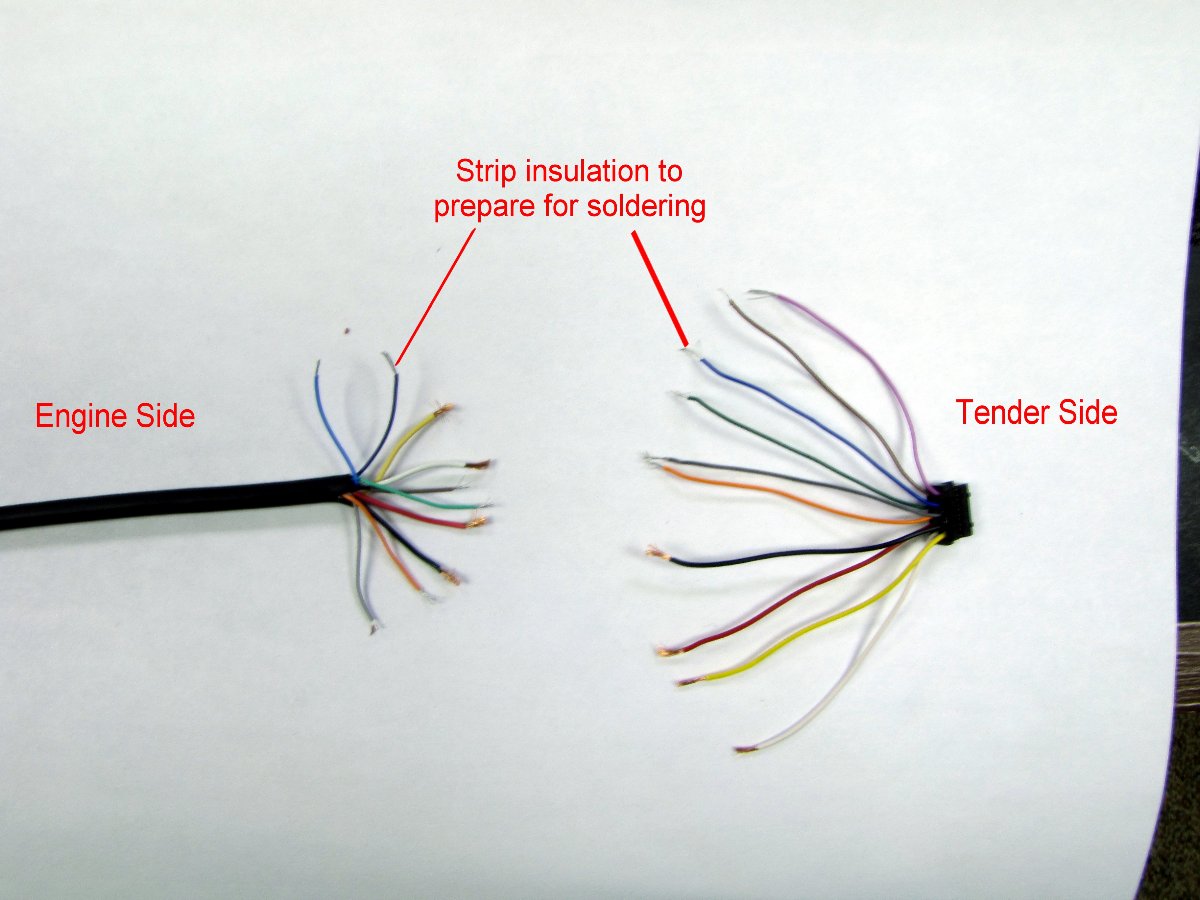
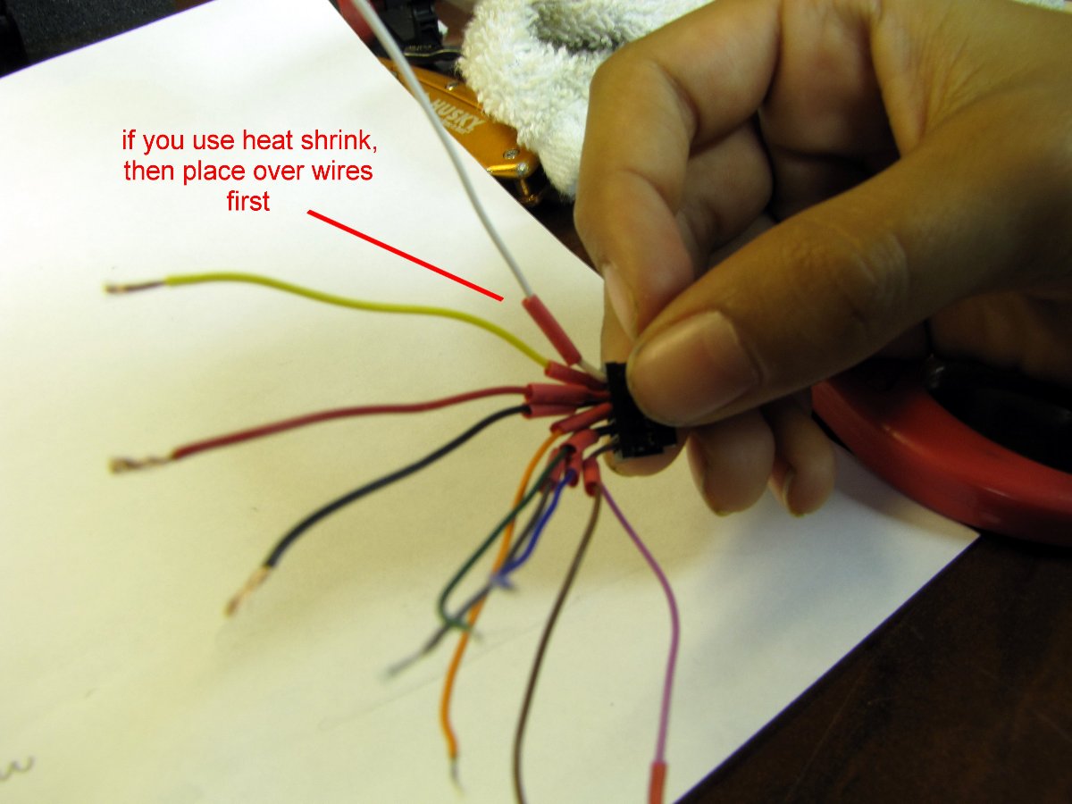
Strip insulation
If you use heat shrink tubing like I did (red sleeves), then place over wires first, away from heat when soldering. Else, you can just use electrical tape.
Map Pins to wire color.
Using the ohmeter as before, determine which color wire belongs to each pin for both the engine side and tender side connector. This table shows the mapping I found for my connectors. It may be the same for you, but you must check.
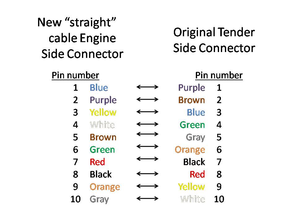
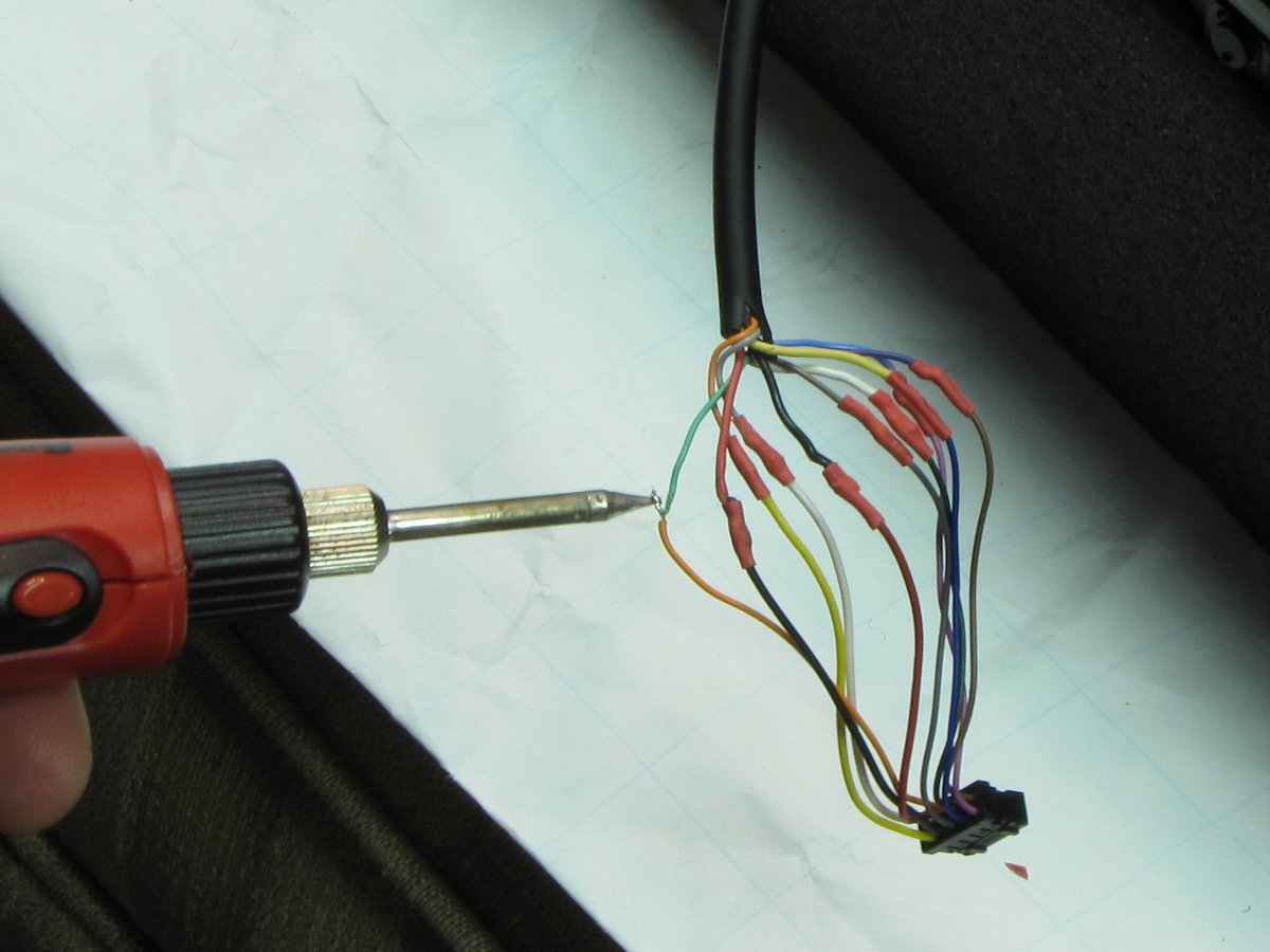
Connect wires.
Twist pairs together, solder, slide heat shrink over solder joint, use solder iron to shrink the shrink tube, or cover with electrical tape.
VERIFY CONNECTIONS!
When done connecting wires, use ohmeter again to check the pin for pin connections between the engine side and tender side connector according to the table. You may also want to verify that each pin is not shorted or connected to another pin.
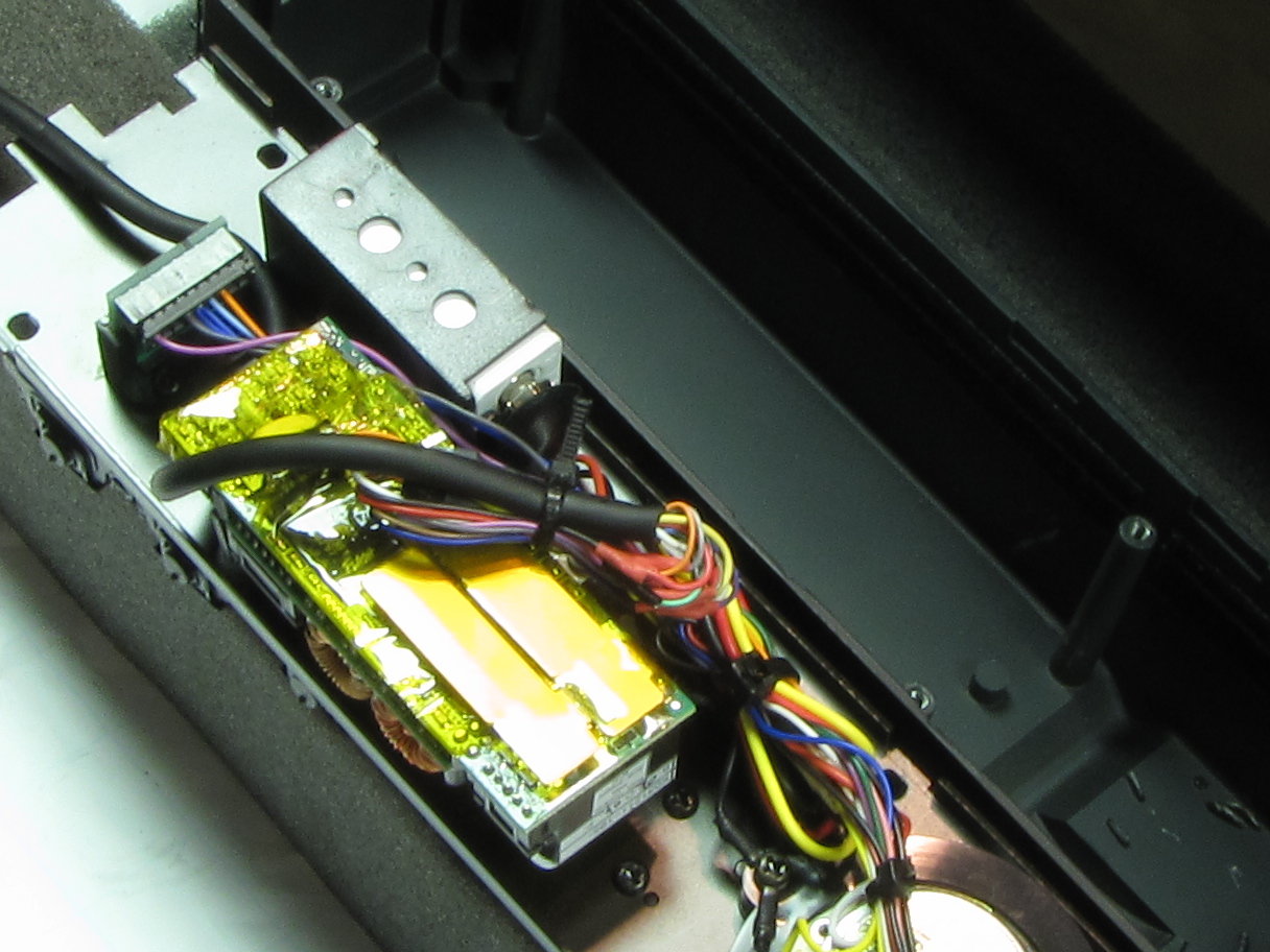
Plug in tender side connector
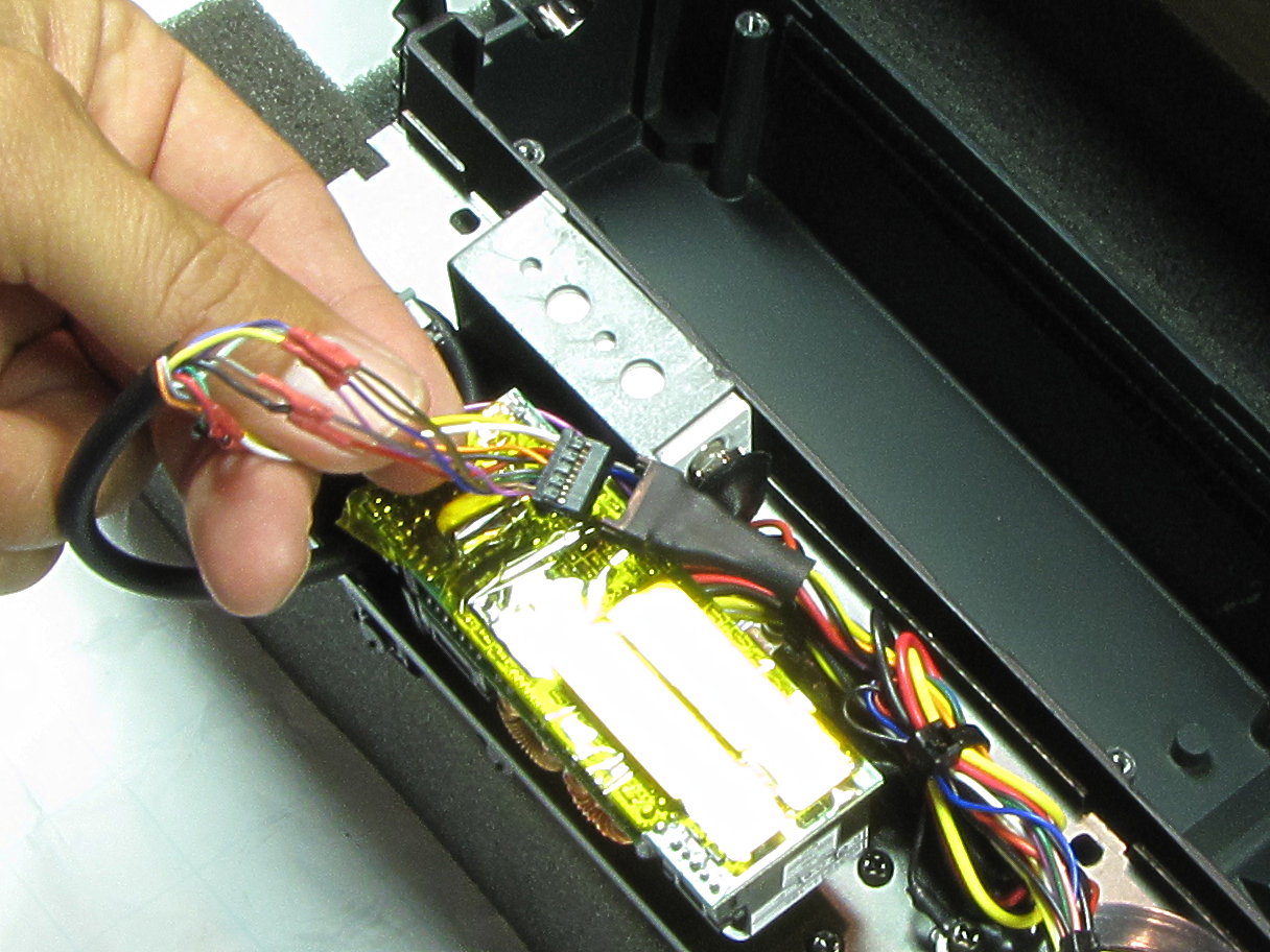
Tie wrap, and then we are finished with the electrical work!
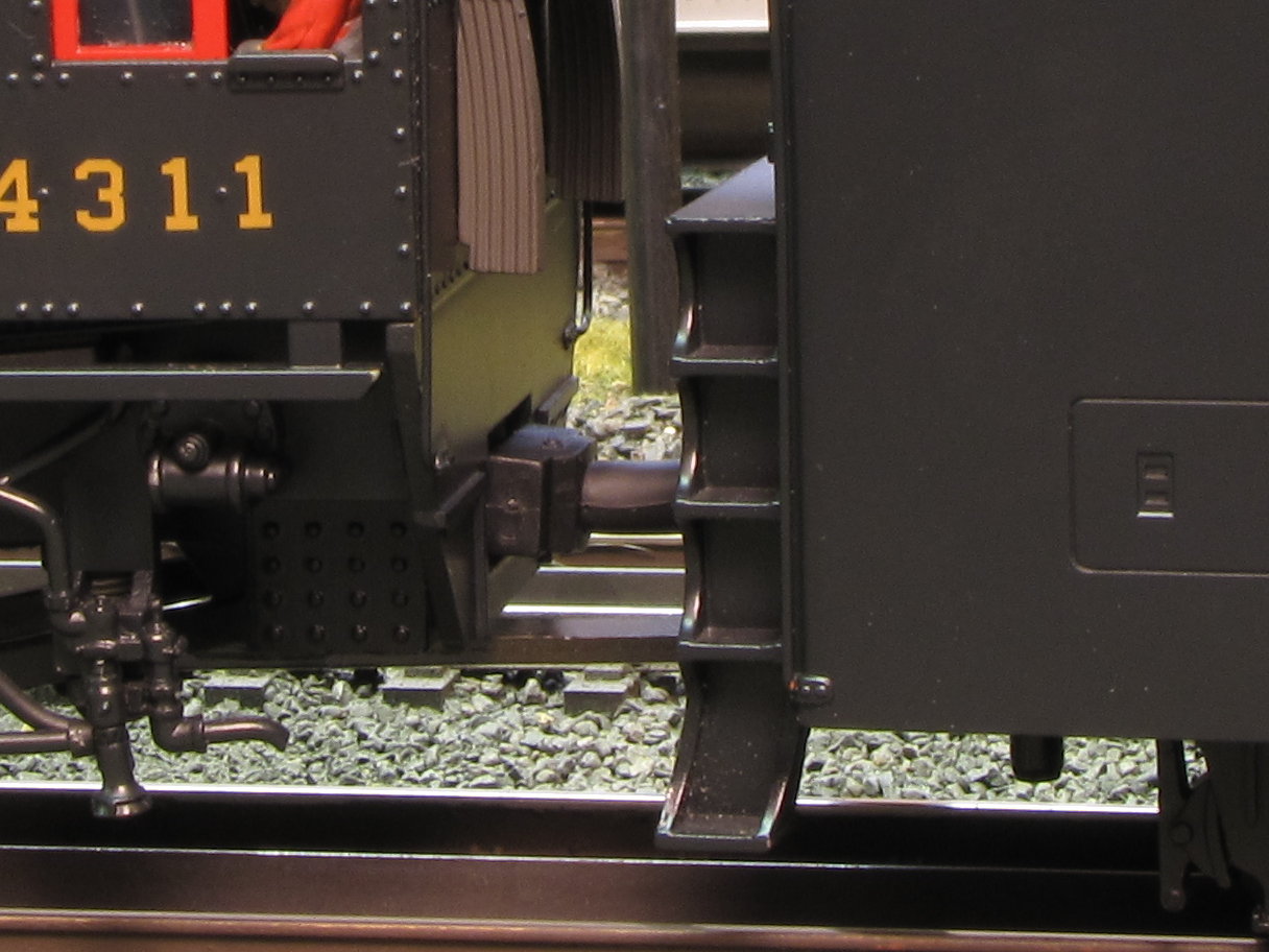
4. Widen hole in tender for tether (Optional)
To allow this modification to work on my only O72 "S" curve (will eventually remove) and to make it more reliable, I widened the opening in the tender where the tether goes through. I highly recommend it. The opening is barely visible and will not be noticed.
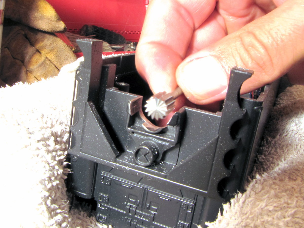
I used a dremel tool and this bit shown in the photo which I bought at Home Depot. This is ideal for making the opening wider. I used this larger bit so the curve in the opening is wide enough not to snag the tether as it moves from side to side.
You can see the clearance in this photo.
You can use black paint or black Sharpie like I did to cover the shiny metal in the opening.
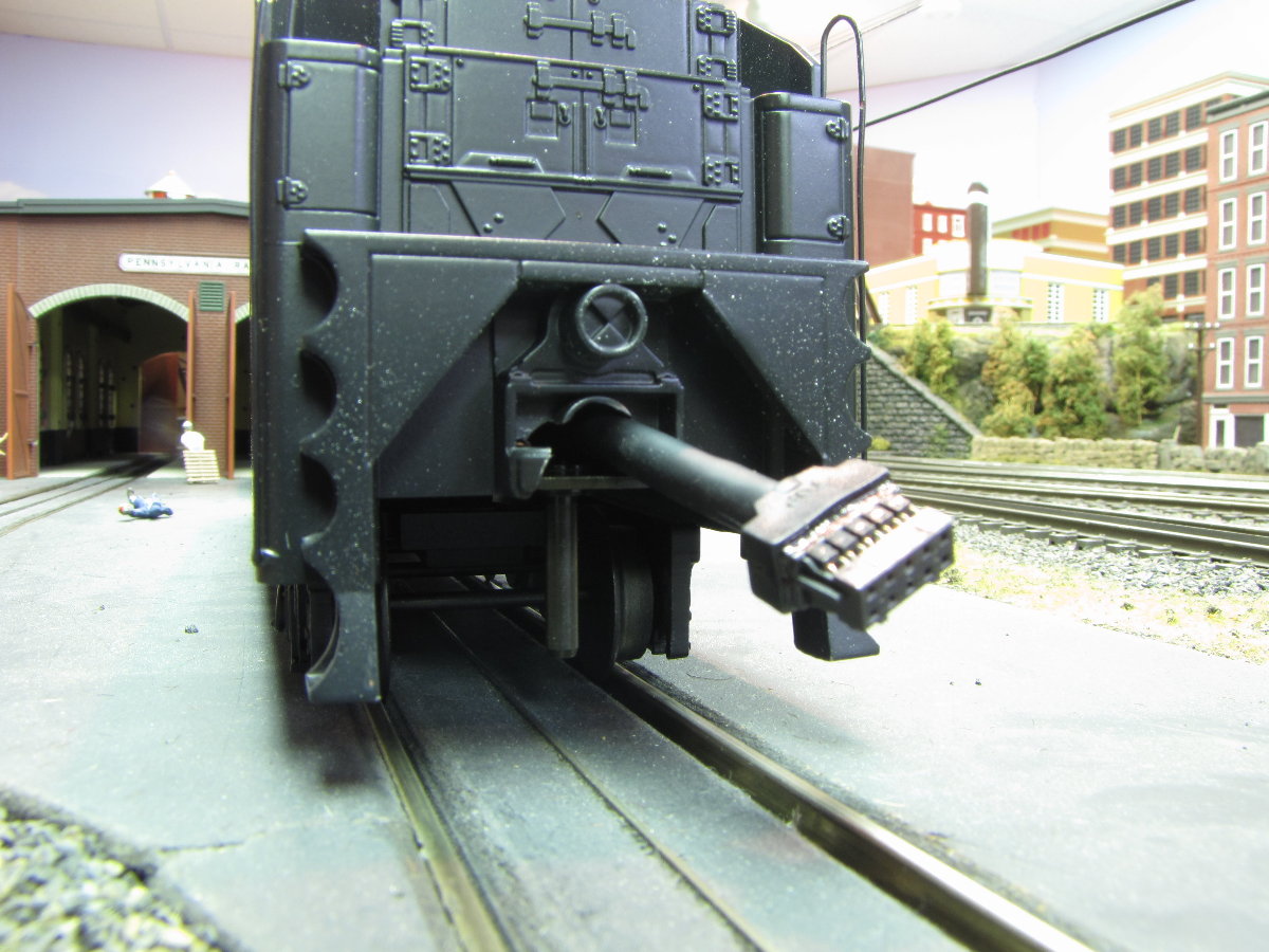
The Final product!
Besides no more un-prototypical curling tether, this straight tether looks like the pipe for feeding coal from the tender to firebox.